Gen5 Timmy Maintenance Guide
Verfasst: 30.12.2007 00:12
For the less mechanically inclined..
What You Need
-Full set of SAE (standard) allen wrenches
-Old squeegee works best as it serves a dual purpose but a wooden rod also works
-Long, thin needle nose pliers
-Q-tips
-Mihau Cum
Before going any further use some common sense and remove your hopper, tank, on/off, rail and macro line.
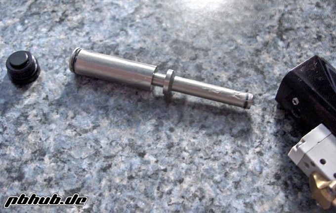
Bolt/Ram
1. Pull up on the bolt pin until is clicks. This disengages it from the ram allowing it to be removed.
2. Remove the bolt from the back of the marker.
3. Wipe off all the nastiness and set aside.
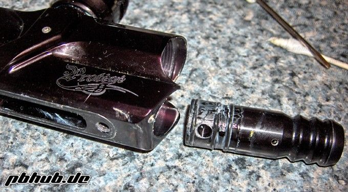
4. Using the appropriate allen wrench unscrew the ram cap from the gun.
5. Tilt the gun back and let the ram slide out into the palm of your hand. The Gen. 5 guns have a bit tighter tolerances than previous generations so you may have to tap the back of the gun with your hand to get the ram out.
6. Wipe off all the nastiness on the ram and ram cap and set aside.
(Note: ram and cap shown cleaned and ready for installation.)
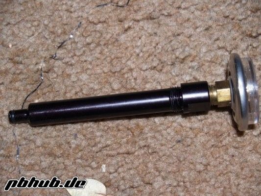
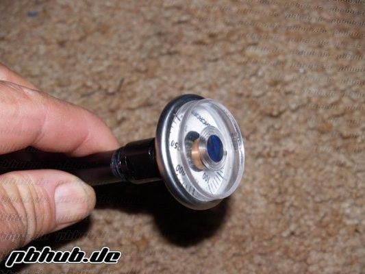
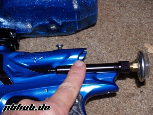
Torpedo
1. Remove the regulator from the gun.
2. The body of the regulator is in 2 halves. Unscrew the two halves and set the top half aside.
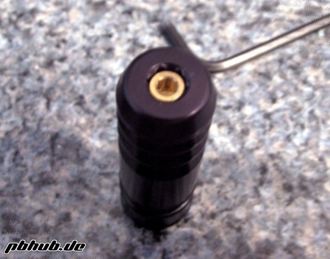
3. Using the appropriate sized wrench turn the adjustment screw all the way in until the piston, shims, and shim holder fall out.
4. Clean all nastiness from inside of the body, the pistion, the shims, and shim holder.
5. Relube the o-ring on the piston only. The shims and shim holder do not need lube.
6. Reinstall the adjustment screw into the bottom of the body and place, in order, the shim holder, the shims and finally the piston (crown side up) into the bottom half of the regulator. The easiest way to do this is the hold the internals of the regulator pre-arranged in one hand and push them up into the lower half of the regulator body. This is easier than attempting to drop the entire stack into the body and hoping it lands in the body flat and in order.
7. To remove the threaded adapter unscrew the two set screws on the top portion of the regulator. It is possible to damage the threaded adapter so fully remove both screws from the body before trying to pull out the adapter. The adapter pulls straight out of the top of the upper regulator body. The o-rings on this part of the regulator seldom need cleaning or relubing. They are purely static sealing surfaces so the only maintenance needed here is a periodic check and a very light re-greasing.
8. Reinstall the threaded adapter into the top half of the regulator body and reinstall the locking set screws. Now apply a small amount of grease to the o-ring on the top half of the regulator body above the threads where the lower half threads onto. Then screw the two halves of the regulator back together ensuring not to crossthread the halves and set aside for final reassembly.
(Exploded view of the Torpedo.)
Frame Removal/Cleaning
1. If you haven't already removed the Torpedo from the gun do so now.
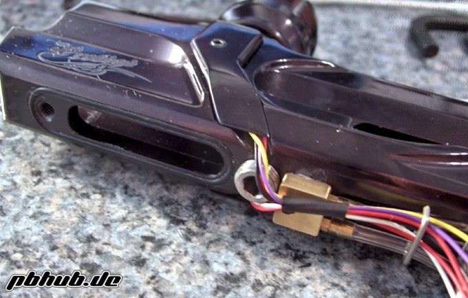
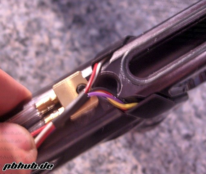
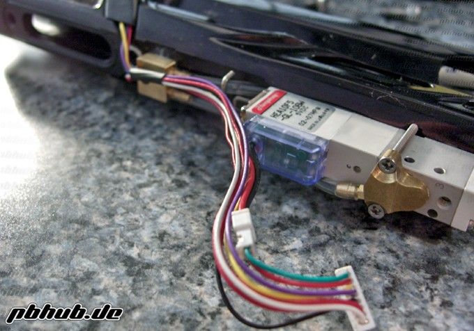
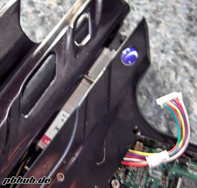
2. Remove the left grip panel, remove the battery, and unplug the wiring harness from the board.
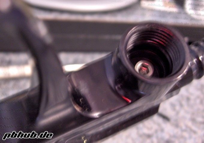
3. Using the appropriate wrench remove the screw inside the reg mount.
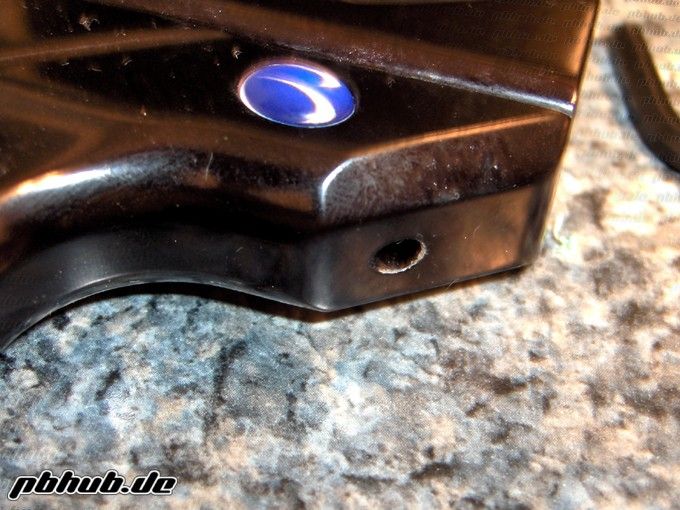
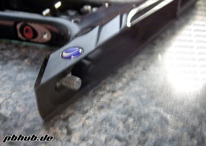
4. Now locating the rear frame screw at the back of the gun. Remove it as well. Note that this screw sits in a recess preventing the frame from being pulled away from the body until it is fully unthreaded.
5. To remove the trigger locate the head of the pin on the left side of the frame. Simply remove the pin and remove the trigger by pulling it towards the guard and out of the frame.
Eyes/Detents
1. Using the appropriate wrench remove the eye covers from the body. Use caution removing these covers as there is a spring underneath that can jump the cover off if not secured.
2. First remove the small detent spring and set aside. Now remove the dome shaped detent. This is easly done by pushing it out with a small allen wrench from inside the breech. Clean the detent itself and the hole it sits it. Set detent aside with the eye cover, eye cover screw, and detent spring.
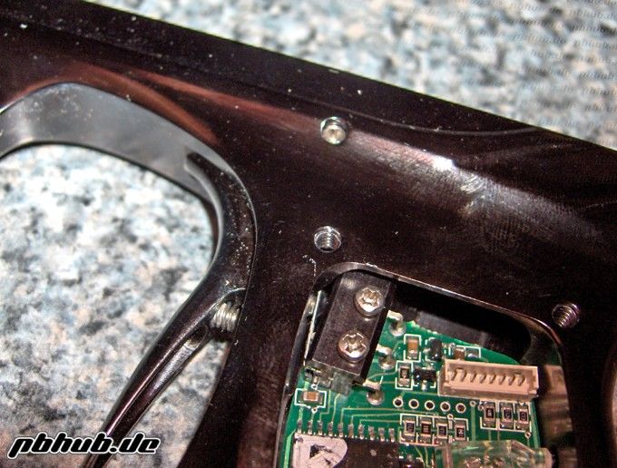
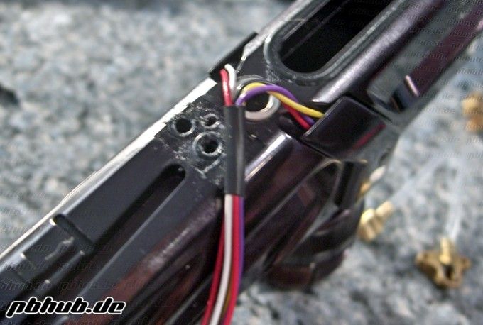
3. Using an electronics Phillips head screw driver remove retaining screw holding the eye board in.
4. Unplug the eye board from the wiring harness and clean.
5. At this time you can clean out the body under the eye cover and holes for the eyes.
6. Reinstall the eye board to the body. Note that the board retaining screw goes through second hole on the eye board. Do not overtighten this screw.
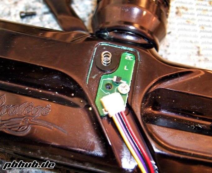
7. Plug the wiring harness back into the eye board.
8. Reinstall the detent and detent spring.
9. Rinstall the eye cover making sure the detent spring does not come out of place and ensure the wiring harness does not get pinched between the eye cover and body.
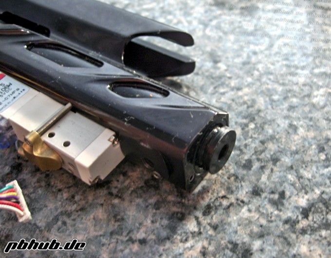
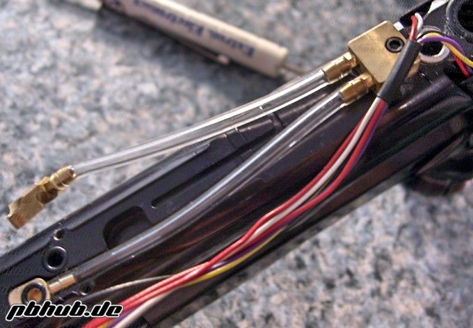
(Note that the left eye board has a connector for a 4 pin plug. The right eye board only has a 2 pin connector.)
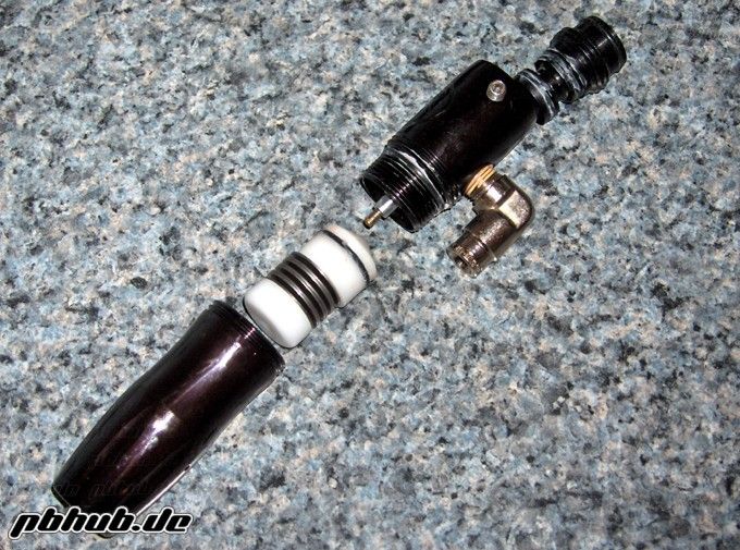
LPR Removal/Cleaning
1. With the frame removed from the gun flip the body over.
2. Grasp the body of the LPR and pull it straight out of the body of the gun. The forward frame screw (the one you remove from inside the reg mount) is the only peice holding the LPR in. The tolerances are tight so it may require some force to remove the LPR.
3. With the LPR out of the body go ahead and remove all the nastiness from the body of the LPR and remove any old grease from the external o-rings.
Note: If you do not have an LPR tester do not fully disassemble the LPR!
4. Using the appropriate wrench back the LPR adjustment screw all the way out. (brass screw in the center of LPR looking at it from the front when installed in the gun)
4. Now using a larger allen wrench unscrew the cap from the LPR body. This may take some force but use caution ensuring that you do not strip out the cap in the process.
5. With the cap removed you will see a small unfinished plate inside the LPR. Simply flip the LPR upside down and allow this plate and the LPR spring behind it to fall out. If there is any debris on either the plate or spring clean them and set aside.
6. Looking inside the LPR body the only peice left is the white LPR piston. Using the needle nose pliers grab the raised cylinder and pull it out of the body of the LPR. Clean the old grease from the piston and set aside.
7. Clean out the inner bore of the LPR body and regrease the o-ring on the piston. Reinstall the LPR piston ,cone shaped face first, into the body followed by the spring and finally the adjustment plate. Reinstall the LPR cap and finally the adjustment screw.
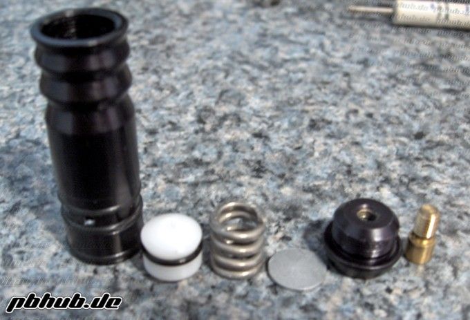
(Parts, in order, of the LPR: LPR body, piston, spring, adjustment plate, cap, and adjustment screw)
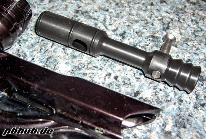
Poppit/Ram Sleeve
1. With the body upside down and the LPR removed use a screwdriver or allen wrench to pull the valve spring off the head of the poppit.
2. Tilt the body foward and tap it to remove the poppit from the sleeve. Clean all old grease and other nastiness from the shaft, o-ring and seating surface of the poppit and set aside.
3. Locate the large stainless ram sleeve alignment screw on the underside of the body and remove it. This screw is right behind the valve chamber gasket.
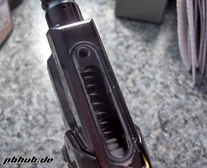
4. With the screw removed push the ram sleeve out of the body using a squeegee or wooden rod. Take extra precaution not to cut any o-rings on any of the windows of the body.
5. With the sleeve removed clean out the inner bore of the body, o-rings on the sleeve, and sleeve itself. Apply a generous amount of grease to all the o-rings on the sleeve. This allows for an easier installation and ensures there is still grease on the o-ring by the time the sleeve is full installed.
6. Install the sleeve with the side with the three o-rings first ensuring the alignment hole is facing down. The sleeve is a tight fit so it may take some force to install. Again, take caution not to cut any o-rings on the windows of the body when reinstalling.
(Install this end first. Note the alignment hole on the sleeve and ensure that it is facing down when installing into the body)
7. Now looking at the bottom of the body align the sleeve alignment hole so that the alignment screw can be installed.
8. Reinstall the sleeve alignment screw. If this screw is hard to install do not force it. Remove the screw and check the aligment of the sleeve and try again. Tighten this screw snugly but do not overtighten as this can make the sleeve leak inside the body.
9. At this point take the clean and re-greased poppit and install it back into the front of the sleeve making sure it is fully seated. Now reinstall the valve spring with the large end facing away from the gun. Ensure that the spring is fully seated on the head of the poppit at this time.
10. Finally reinstall the cleaned and regreased ram, narrow end first, into the rear of the ram sleeve and reinstall the cap.
(LPR installation will be covered later on.)